
Understanding LED PCB Basics
When designing LED circuit boards, it’s important to know how LED PCBs differ from standard PCBs. Unlike general-purpose boards, LED PCBs focus heavily on heat management and electrical efficiency to ensure long-lasting performance and consistent brightness.
Differences Between Standard PCBs and LED PCBs
| Feature | Standard PCBs | LED PCBs |
|---|---|---|
| Primary focus | Signal routing and component support | Heat dissipation and power handling |
| Heat management | Limited or passive | Critical with specialized materials |
| Layer complexity | Varies (single to multilayer) | Often includes metal-core layers |
| Electrical load | Moderate to low | High current for LED operation |
Types of LED PCBs
- Single-layer PCBs: Basic design for low-power LEDs; simple and cost-effective.
- Multilayer PCBs: Used in complex LED configurations needing multiple connections.
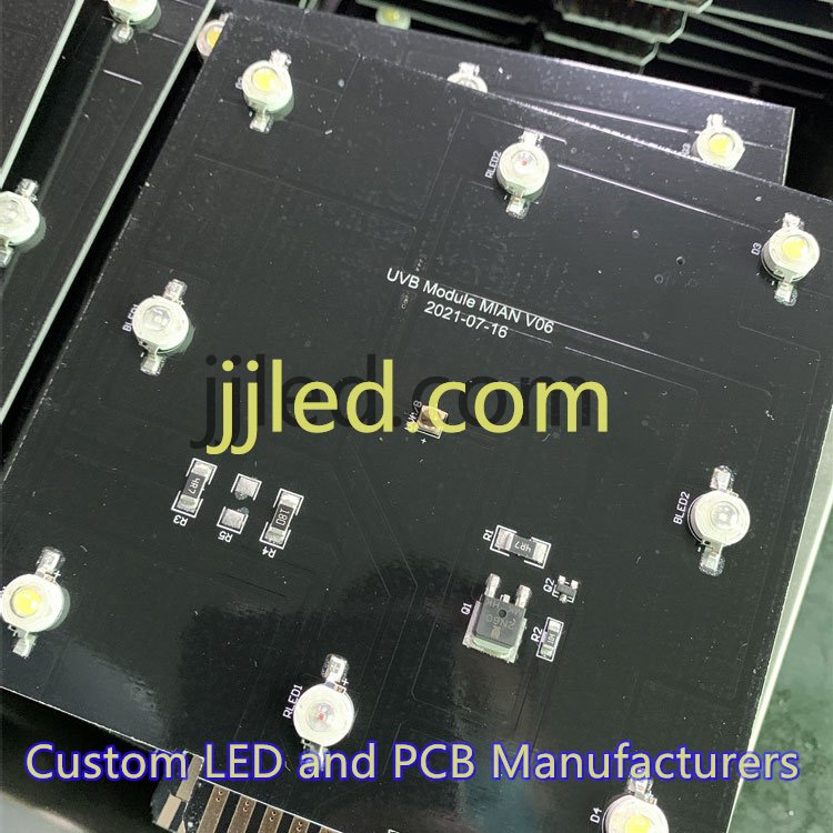
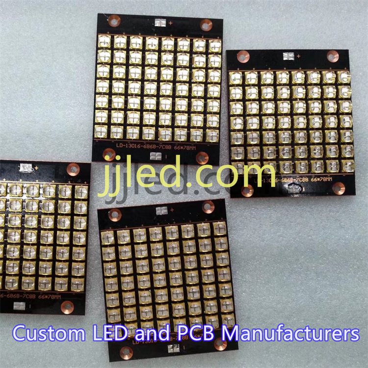
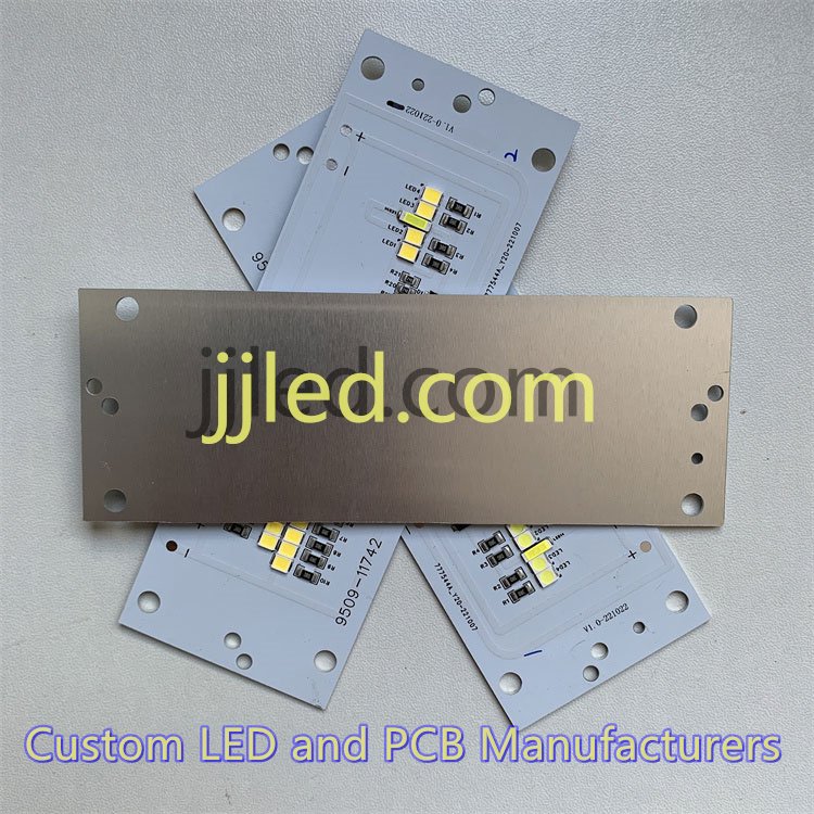
- Metal-core PCBs (MCPCB): Incorporate aluminum or copper cores for superior heat dissipation.
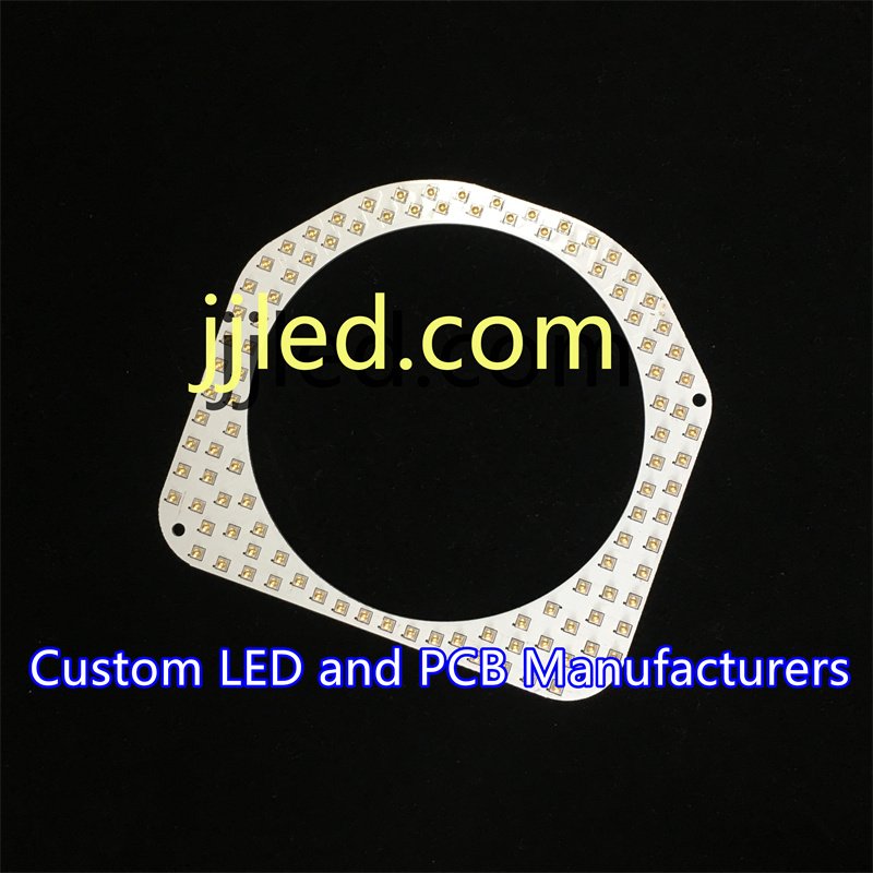
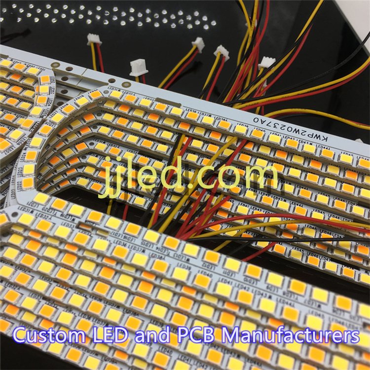
- Flexible PCBs: Ideal for curved or compact LED applications.
- Hybrid PCBs: Combine rigid and flexible layers for versatile solutions.
Why Specialized LED Boards Matter
Specialized LED PCBs excel in two main areas:
- Heat Dissipation: Metal-core boards and thermal vias transfer heat away from diodes, increasing lifespan.
- Electrical Performance: Wider copper traces and optimized layouts reduce voltage drops and improve reliability.
Understanding these fundamentals helps you choose or design LED PCBs that keep your lighting bright, cool, and efficient—key for all your projects.
Material Selection for LED Circuit Boards
Choosing the right materials is key for effective LED PCB design. For low-power LEDs, FR4 substrates are common because they’re affordable and easy to work with. But when you’re dealing with high-power LEDs, aluminum or copper-core boards are much better. These metal-core PCBs (MCPCBs) handle heat way more efficiently, which is crucial since LED performance drops and lifespan shortens when they get too hot.
Metal-core boards excel because they offer higher thermal conductivity than standard FR4. This means heat generated by the LED chips moves away quickly, keeping everything cooler and more reliable. When picking your metal core, aluminum is widely used for balancing cost and heat dissipation, while copper offers even better thermal performance but at a higher price.
Some other important factors include:
- Copper thickness: Thicker copper layers improve current capacity and heat spreading. For high-power LED layouts, 2oz or more copper thickness is typical.
- Dielectric Layers: The insulating layer between the metal core and copper traces must be thin and have good thermal conductivity to support heat transfer.
- Surface Finishes: Finishes like ENIG (Electroless Nickel Immersion Gold) or HASL (Hot Air Solder Leveling) affect solderability and long-term durability. ENIG offers a flat, reliable surface for better solder joints and corrosion resistance.
Balancing cost, thermal performance, and manufacturability is essential — especially for global customers who need both quality and affordability. Using metal-core PCBs wisely ensures your LED circuit boards deliver consistent brightness and longer life without blowing the budget.
Thermal Management Strategies for LED Circuit Boards
Heat is the biggest challenge in any LED design. Too much heat reduces brightness, shortens the lifespan, and can even cause failure. Managing this heat well is key to a reliable and efficient LED PCB.
Here are the main ways we handle thermal management:
- Thermal Vias: These small holes connect the top layer of the PCB to inner or bottom layers, helping to spread heat away from the LEDs faster.
- Heat Sinks: Attaching metal heat sinks to the board pulls heat away, keeping temperatures down.
- Copper Pours and Large Ground Planes: Using bigger areas of copper on the PCB helps spread heat more evenly and reduces hot spots.
- Metal Core PCBs (MCPCBs): These boards have a metal base (usually aluminum) that acts like a heat pipe, quickly conducting heat away from the LED components.
Calculating thermal resistance and monitoring junction temperature is crucial. These values tell us how well the board manages heat and help keep LED temps within safe limits. Reliable thermal management means brighter, longer-lasting LEDs without costly failures.
Component Placement and Layout for LED PCB
Placing components right is key to a reliable and efficient LED circuit board. Here’s what we focus on:
- Optimal LED spacing ensures even light distribution and cuts down on hotspots. Too close, and you get uneven brightness; too far, the light spreads too thin.
- Logical grouping of parts helps simplify assembly and keeps electrical noise low. Group LEDs, resistors, and drivers so wiring stays neat and interference is minimal.
- Trace routing matters a lot, especially for high-current paths. Use wider copper traces to handle the current, reduce voltage drops, and avoid overheating. Keep sensitive signals away from noisy power lines to maintain signal integrity.
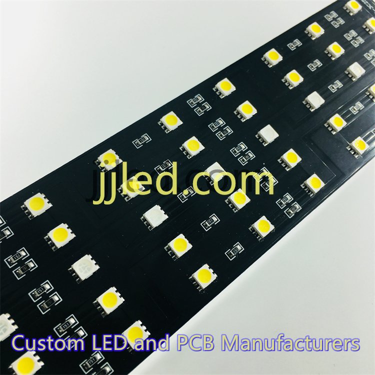
- When choosing between SMD LEDs and through-hole, consider your application. SMDs are more compact and easier for automated assembly, but through-hole might work better for robust mechanical connections in some designs.
- Driver integration should be close to LEDs to reduce power losses and improve response. This also makes troubleshooting and testing easier.
Overall, good component placement and layout balance performance with manufacturability, helping the LED board last longer and work better under various conditions.
Electrical Design Considerations for LED Circuit Boards
When designing LED circuit boards, getting the electrical side right is essential for performance and longevity. The power supply and driver circuitry play a big role here. You generally choose between constant current and constant voltage drivers. Constant current drivers keep the LED current steady, which is ideal for most LEDs to prevent flickering and protect from overcurrent. Constant voltage drivers work better when you have many LEDs wired in parallel, but they often need additional current regulation.
Next up is how you arrange your LEDs—series vs. parallel configurations. Series wiring means the same current flows through all LEDs, improving reliability and making current control easier. However, if one LED fails, the whole string can go out. Parallel wiring keeps LEDs independent but requires careful current balancing to avoid uneven brightness or early failures.
To ensure smooth operation, focus on EMI reduction and signal integrity. Use wide ground planes and good trace layout to reduce noise and interference, especially if your LED driver or control signals are sensitive. Proper grounding also helps avoid flicker and unpredictable behavior.
Finally, include overvoltage protection and current limiting features. These prevent damage during power surges or unexpected input changes. Components like fuses, transient voltage suppressors (TVS), or resistors can protect your LEDs and driver circuitry from costly failures.
Key takeaways for electrical design:
- Choose constant current drivers for stable brightness; use constant voltage carefully.
- Series wiring improves reliability but watch for string failures.
- Parallel wiring needs balanced current paths.
- Use ground planes and smart trace routing to cut EMI.
- Add protection circuits to guard against overvoltage and excess current.
By carefully managing these electrical aspects, your LED PCB design will be reliable, efficient, and ready for various global applications.
Optical and Mechanical Aspects of LED PCB Design
To get uniform LED illumination, the placement and shape of the board are key. Proper spacing between LEDs reduces hotspots and ensures even light spread. The board’s layout should accommodate the way light moves, so think about how placing LEDs in patterns or clusters affects brightness.
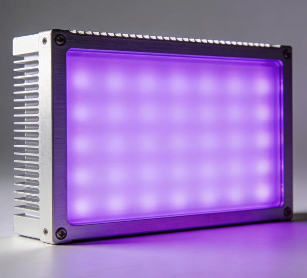
Adding optical elements like lenses, diffusers, or reflectors can improve light distribution. Lenses help focus or spread the beam, diffusers soften harsh light, and reflectors bounce light where needed—all boosting overall performance without changing the electrical setup.
Board size and shape matter too, depending on the application: strips for flexible lighting, panels for large areas, or fixtures for specific mounting needs. Designing the PCB to fit the final product’s shape helps with easy installation and better mechanical stability.
Key points to consider:
- Arrange LEDs evenly to avoid hot spots
- Use lenses, diffusers, or reflectors to shape the light
- Choose board size and shape to suit the product’s use (strips, panels, fixtures)
- Design mounting holes or clips for secure installation
By focusing on these optical and mechanical factors, you’ll create efficient LED PCBs that deliver consistent light and fit well in their final applications.
Manufacturing and Testing Best Practices for LED PCB
When it comes to manufacturing LED circuit boards, following Design for Manufacturability (DFM) rules is essential. Pay close attention to pad sizes and solder mask application—these ensure reliable solder joints and make assembly easier. Prototyping early lets you spot issues before full production.
Watch out for common pitfalls like:
- Circuit scratches that can break connections
- Poor solder joints causing electrical failures
- Inadequate vias that reduce heat dissipation and signal quality
Testing plays a big role in quality control. Use thermal imaging to check how well your LED PCB manages heat. Measure electrical performance to spot shorts or voltage drops. Finally, run reliability checks to confirm the board holds up over time under real conditions.
Following these best practices guarantees a durable LED PCB that performs consistently for global customers demanding high-quality, efficient lighting solutions.
Cost vs. Performance Trade-offs in LED PCB Design
When designing LED circuit boards, finding the right balance between cost and performance is key. Using high-quality materials like aluminum or copper-core substrates and adding features such as thermal vias or thicker copper layers can increase upfront costs. However, these choices dramatically improve heat dissipation, electrical reliability, and the overall lifespan of your LED board.
Here’s how to approach the trade-off smartly:
- Budget wisely: For low-power projects, FR4 boards might be enough and keep costs down. But for high-power LEDs, investing in metal core PCBs (MCPCBs) makes sense to avoid failures and reduce maintenance.
- Focus on efficiency: Better thermal management reduces energy waste and prevents brightness loss, saving money in the long run.
- Consider reliability: Using quality proper driver circuitry reduces downtime and warranty claims.
- Plan for scale: Custom LED PCB manufacturing might cost more initially but offers better consistency and fewer defects over mass production.
In short, spending a bit more on advanced features and materials upfront leads to LEDs that run cooler, last longer, and deliver consistent performance—offering real value to global users looking for durability and energy savings.
