
If you’re designing LED lighting, nailing the LED driver circuit design is non-negotiable. Without the right driver, your LEDs won’t just underperform—they risk damage from improper current or voltage. Whether you’re powering a simple indicator or building a high-power array, understanding how to create efficient, stable, and safe LED drivers makes all the difference. In this guide, you’ll get clear, practical insights on everything from basic resistor calculations to advanced switching topologies. Ready to master LED driver circuits and build lighting solutions that last? Let’s get started.
Fundamentals of LED Drivers
Understanding how LEDs work is essential for effective LED driver circuit design. LEDs require a specific forward voltage (Vf) and a controlled forward current (If) to operate safely and efficiently. The Vf is the voltage needed to make the LED emit light, typically between 1.8V to 3.3V depending on the LED color and type. The If is critical because LEDs are current-sensitive devices—too much current can damage or reduce their lifespan.
Forward Voltage (Vf) and Forward Current (If)
- Forward Voltage (Vf): The minimum voltage to turn the LED on.
- Forward Current (If): Must be controlled precisely to avoid overheating or failure.
- LEDs do not behave like resistors; their resistance changes with temperature and current, so current regulation is key.
Constant Current vs. Constant Voltage Drivers
Choosing the right LED driver type depends on your application:
- Constant Current LED Drivers: Provide a steady current regardless of voltage changes. Ideal for powering LEDs because they protect against overcurrent and ensure uniform brightness.
- Constant Voltage LED Drivers: Maintain a fixed voltage output, commonly used for LED strips with built-in resistors or multiple LEDs in parallel.
When to use which?
- Use constant current drivers for high-power discrete LEDs or arrays.
- Use constant voltage drivers for low-power LED strips or modules designed for fixed voltage.
Key Risks in LED Driving
Proper LED driver design must address several risks:
- Overcurrent: Can cause irreversible LED damage or thermal runaway.
- Thermal Runaway: A dangerous condition where rising temperature lowers LED resistance, increasing current and heat further.
- Voltage Fluctuations: Can lead to unstable brightness and reduced LED life.
Practical Tip: Always design your LED driver circuit to regulate current precisely and include safety margins for voltage and temperature variations to ensure reliable, long-lasting LED performance.
By mastering these fundamentals, you lay a solid foundation for designing efficient, safe, and reliable LED drivers tailored to your specific application.
Basic LED Driver Circuits
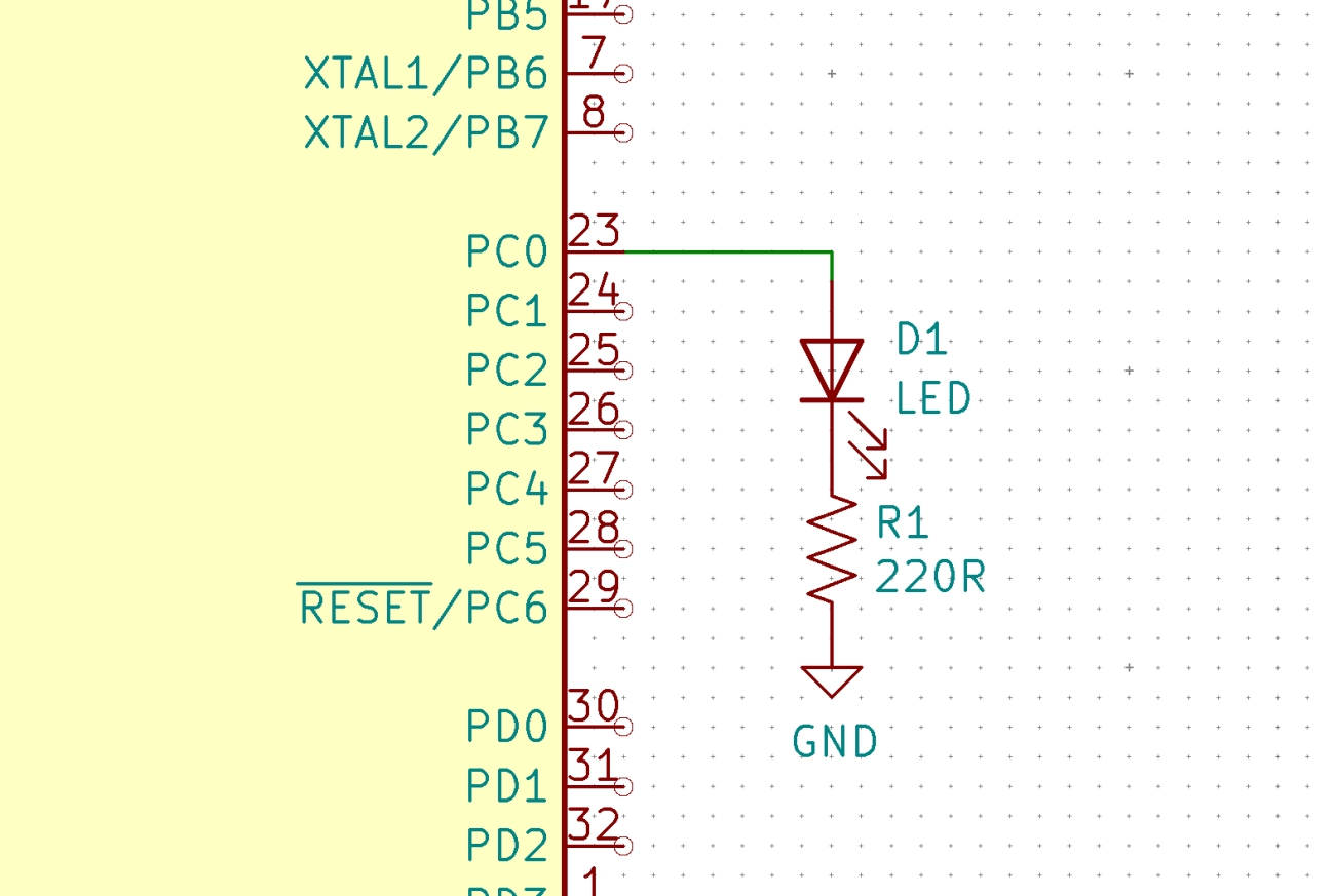
Starting with simple LED driver circuit design, the most basic method uses a resistor in series with the LED to set the current. You calculate the resistor value by subtracting the LED’s forward voltage (Vf) from the supply voltage, then dividing by the desired forward current (If). While this is easy and cheap, it’s not very efficient or precise. Resistor-based drivers don’t adjust for voltage or temperature changes, which can cause uneven brightness or even damage if the current spikes.
A step up from resistors are linear regulators like the popular LM317. Configured as a constant current source, the LM317 maintains a steady current to the LED, improving stability and safety. These linear LED regulators are simple to design and provide better protection compared to resistors, but they waste power as heat, especially with high input-output voltage differences. That makes them less ideal for high-power LED driver circuits.
For more refined control, discrete transistor-based constant current sources use transistors and reference voltages to regulate LED current. They offer a balance between simplicity and performance, often featured in small LED driver circuits. However, they still suffer from heat dissipation and lower efficiency compared to switching drivers.
While basic LED drivers are great for low-power or simple applications, they come with clear limits in precision, efficiency, and thermal management. For advanced or high-power LEDs, switching LED driver circuits provide better performance.
For a practical guide on basic LED circuits and PCB assembly, you might want to explore our detailed LED light circuit board design resources.
Switching LED Driver Topologies

Switching LED driver circuits are popular for their efficiency and versatility, especially in high-power LED applications. Here are some common topologies you’ll encounter:
- Buck Converters: Ideal for driving high-power LEDs, buck converters step down a higher input voltage to a stable lower LED forward voltage. They provide a constant current output with high efficiency, making them perfect for 10W+ LED drivers and other demanding loads.
- Boost Converters: When your power source voltage is lower than the LED’s forward voltage, a boost converter comes in handy. It steps up the voltage while regulating current, especially useful for low-input voltage setups like battery-powered LED strips.
- Buck-Boost and SEPIC Converters: These topologies handle scenarios where the input voltage fluctuates above and below the LED forward voltage. They offer flexible input ranges without dropping brightness or risking damage, suitable for variable power supplies.
- Flyback Converters: For isolated LED driver designs, especially those linked directly to AC mains, flyback topology provides electrical isolation and efficient power conversion. It’s often found in transformerless LED driver circuits and high-voltage applications.
Choosing the right switching LED driver depends on your LED’s power requirements, input voltage, and whether isolation is needed. For detailed design tips on LED circuit boards, exploring specialized resources like design considerations for LED circuit boards can be very helpful.
These topologies ensure your LED driver delivers steady, reliable current while maximizing efficiency and maintaining safe operation.
Component Selection and Calculations for LED Driver Circuits
Choosing the right components is crucial in LED driver circuit design to ensure reliability, efficiency, and longevity. Here’s a quick guide on what to focus on:
- Inductors and Capacitors: Select inductors with low DC resistance and sufficient current rating to reduce losses in switching LED drivers like buck or boost converters. Capacitors should have low Equivalent Series Resistance (ESR) and be rated for the operating voltage and ripple current to smooth output voltage and minimize flicker.
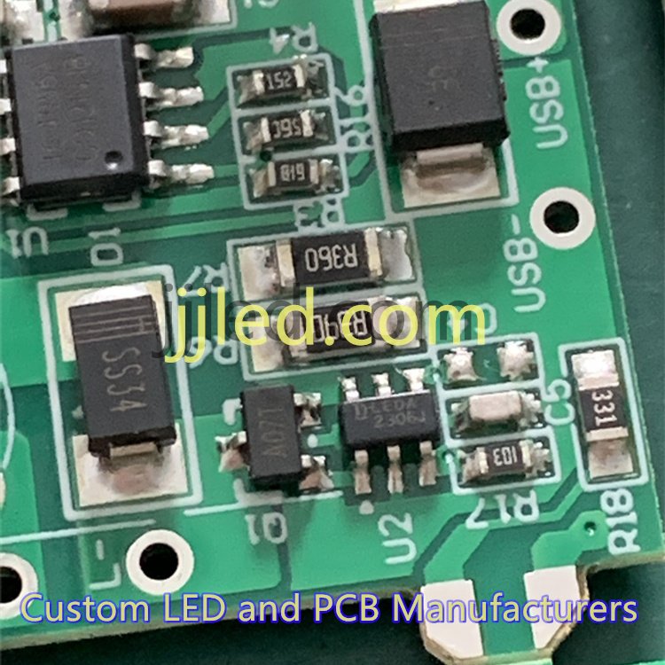
- MOSFETs and Diodes: Use MOSFETs with low R_DS(on) for higher efficiency and fast-switching capabilities. Diodes, especially Schottky types, are preferred in switching LED drivers for their low forward voltage drop and fast recovery time, enhancing overall performance.
- Current Sensing Resistors and Feedback Loops: Accurate current sensing resistors are key to maintaining constant current in LED drivers. Feedback loops using these sensors help regulate the LED current precisely, protecting LEDs from overcurrent issues and ensuring stable brightness.
- Efficiency, Ripple, and Power Dissipation: Calculate efficiency based on power in versus power out, minimizing losses in components. Control output ripple through proper filtering to avoid uneven LED brightness. Power dissipation formulas help determine thermal stress on components, guiding cooling solutions.
- Thermal Management: Heat is a common enemy in high-power LED drivers. Incorporate heatsinks and design your PCB layout to maximize heat dissipation. Spread components to avoid hotspots, improve airflow, and use thermal vias where necessary to maintain stable operating temperatures.
Choosing the right parts combined with careful calculations can significantly enhance the performance and lifespan of your LED driver. For detailed component options and professional PCB assembly services, check out our LED PCB board solutions and custom LED driver circuit design offerings.
Advanced Features in LED Driver Design
Modern LED driver circuit design goes beyond just powering LEDs—it’s about control, safety, and efficiency. Here are key advanced features to consider:
Dimming Methods
| Method | Description | Best For |
|---|---|---|
| PWM | Pulses power on/off rapidly to dim | Precise brightness control |
| Analog | Varies current continuously | Smooth dimming, simple |
| TRIAC | Cuts AC waveform for dimming | Mains-powered dimmable LEDs |
PWM dimming LED drivers are popular since they maintain LED efficiency while allowing fine brightness steps. TRIAC dimming suits transformerless LED drivers used in AC mains lighting.
Protection Circuits
Protect your LEDs and drivers with built-in safety mechanisms:
- Overvoltage protection: Prevents damage from voltage spikes.
- Overcurrent protection: Limits current to avoid burning LEDs.
- Short-circuit protection: Shuts down driver if output is shorted.
- Open-load detection: Recognizes broken LED strings or failures.
These features extend lifespan and reliability, especially in harsh or variable electrical environments.
Power Factor Correction (PFC)
For AC-input LED drivers, power factor correction improves efficiency by reducing reactive power draw. This means less energy wasted and compliance with regulatory standards for commercial applications.
Dimmable & Smart Driver Integration
Smart LED drivers now integrate dimmable control with communication protocols (like DALI or Zigbee). This enables remote, automated lighting adjustments and energy savings—ideal for smart building solutions.
When designing your next LED lighting system, keep these advanced features in mind for robust performance and versatility. For integrated options, explore our custom LED driver circuit design and PCB assembly services tailored to modern needs.
To optimize your design further, visit our detailed guides on red, white, and blue LED lights and how aluminum PCBs improve thermal management in LED applications.
Practical Design Examples of LED Driver Circuits
When designing LED driver circuits, practical examples help translate theory into real-world solutions. For low-power needs like indicator lights or small LED strips, a simple constant current driver using a linear regulator or resistor-based approach often works well. These designs are cost-effective and easy to implement but best suited for LEDs under 1W.
For high-power LEDs of 10W or more, switching LED driver topologies such as buck LED driver circuits are preferred. They efficiently handle higher currents while maintaining stable forward current and preventing thermal runaway. Using dedicated LED driver ICs in these designs improves reliability and simplifies thermal management.
When dealing with AC mains inputs (230V/120V), transformerless LED driver circuits come with unique safety considerations. Protection against overcurrent and voltage fluctuations is critical here, typically involving isolation, surge protection, and careful PCB layout. These designs reduce size and cost but require rigorous adherence to safety standards.
For multi-channel LED drivers, especially for RGB or RGBW LED configurations, drivers must support precise current control on each channel, often with integrated PWM dimming capability. This ensures smooth color mixing and uniform brightness across all colors, ideal for decorative or stage lighting.
If you\’re looking for tailored solutions, we specialize in custom LED driver circuit design and PCB assembly services, providing optimized drivers for varying power levels and configurations. Our expertise includes designing efficient, reliable, and safe LED drivers that fit your specific project requirements.
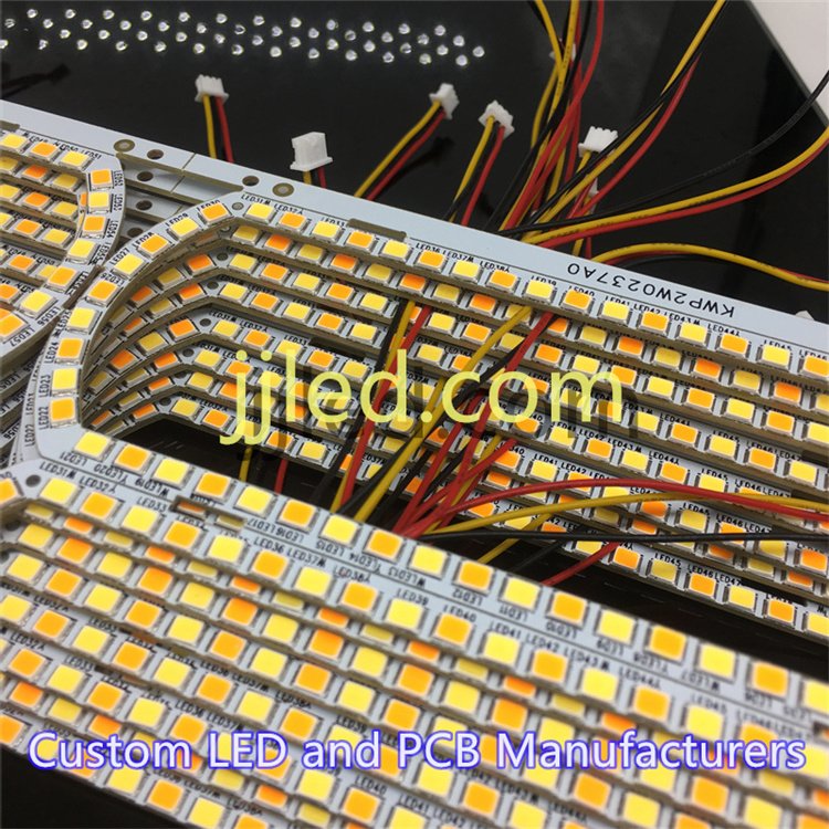
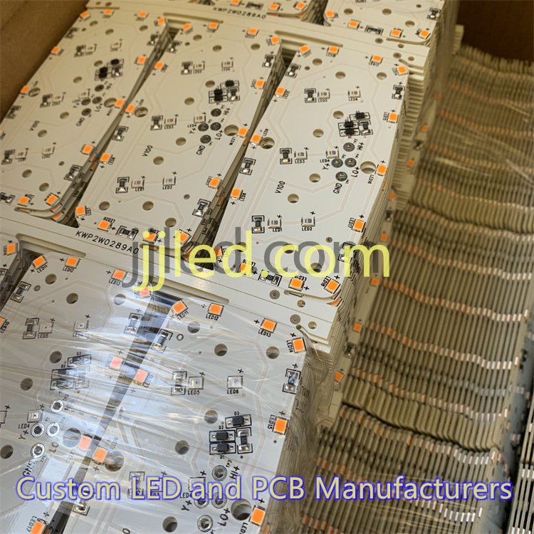
Explore more about our 2835 SMD LED chip options perfect for indicator and low-power applications or visit our blog for insights on lighting technologies at JJLED blog.
PCB Layout and Manufacturing Best Practices
A well-planned PCB layout is crucial for a reliable LED driver circuit design. Proper component placement and routing help minimize electrical noise and heat buildup, which can degrade performance or damage sensitive parts.
Key Layout Tips to Minimize Noise and Heat
- Keep high-current paths short and wide to reduce resistance and heat.
- Separate power and ground planes to improve current flow and reduce EMI.
- Place decoupling capacitors close to IC pins for stable voltage.
- Use thermal vias and copper pours under heat-generating components like MOSFETs or drivers to aid heat dissipation.
EMI Considerations and Grounding
EMI can disrupt LED driver operation and nearby electronics. To control this:
- Implement a solid grounding scheme with a dedicated ground plane.
- Avoid ground loops by carefully assigning star grounding points.
- Shield sensitive signals and separate noisy switching nodes.
From Prototype to Production
Scaling from prototype to full-scale manufacturing requires attention to design for manufacturability (DFM). At this stage, we offer custom LED driver circuit design and PCB assembly services to ensure your product meets quality and consistency standards. This includes:
- Optimizing PCB size and layer stack-up for cost and performance.
- Specifying suitable components and packages for automated assembly.
- Testing and verifying designs before mass production runs.
For professional results, integrating well-engineered PCB layouts with expert manufacturing is key. To learn more about our manufacturing capabilities and how we support projects from concept to completion, check out our detailed guide on how LED PCBs are manufactured.
By following these PCB layout and manufacturing best practices, your LED driver circuits will perform efficiently, safely, and reliably in real-world conditions.
Testing, Troubleshooting, and Optimization
When working with LED driver circuit design, testing and troubleshooting are crucial to ensure reliable performance. Common issues you might face include flickering LEDs, overheating drivers, and uneven brightness across the LED array. These problems often stem from insufficient current regulation, thermal management faults, or poor PCB layout.
Common Issues and Fixes:
- Flickering: Usually caused by unstable power supply or poor PWM dimming signals. Check your constant current LED driver and ensure proper filtering.
- Overheating: Often due to inadequate thermal management or component overload. Use thermal management LED solutions like heatsinks and optimize PCB layout for better heat dissipation.
- Uneven brightness: Can result from voltage fluctuations or inconsistent current distribution. Verify your current sensing resistors and feedback loop accuracy.
Tools for Measurement:
- Oscilloscope: To observe switching waveforms and detect ripple or noise in the LED driver circuit.
- Multimeter: Useful for measuring forward voltage (Vf), current (If), and verifying steady operation.
- Thermal camera: Helps spot hotspots and assess the effectiveness of your thermal management.
Efficiency Improvements:
- Optimize switching LED driver topologies by selecting the right MOSFETs and inductors.
- Fine-tune feedback loops to stabilize current output.
- Minimize power dissipation by improving PCB layout and component placement.
- Consider using advanced LED driver ICs that offer built-in protections and efficiency-boosting features.
For professional-grade troubleshooting and custom solutions, our team offers comprehensive custom LED driver circuit design and PCB assembly services to help you optimize performance and reliability. Explore our detailed LED driver schematics and designs on the custom LED board page to see how we implement efficient, robust circuits for various applications.
