
Fundamentals of LED PCB Design
What is an LED PCB?
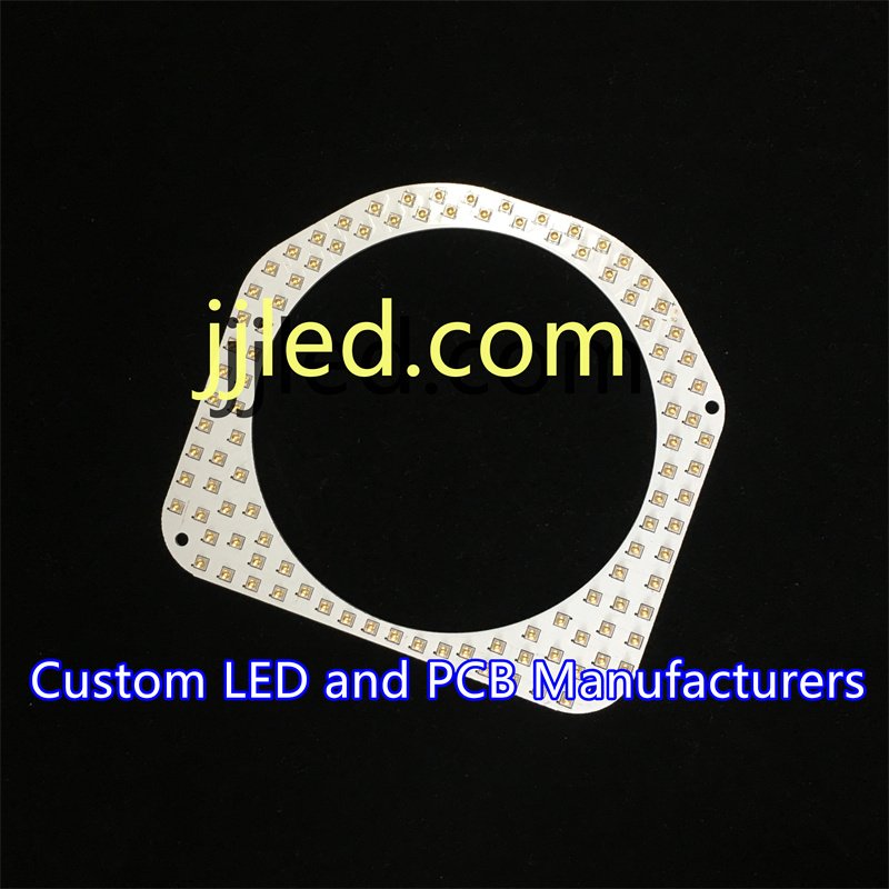
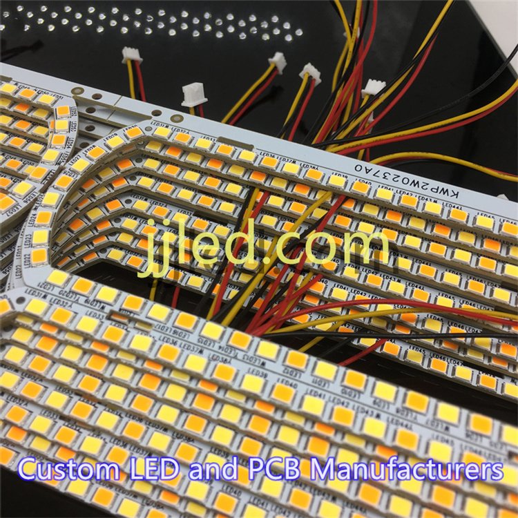
An LED PCB (Printed Circuit Board) is the backbone of any LED lighting system, providing mechanical support and electrical connectivity to LED components. It typically consists of three core parts:
- Substrate: The base layer that supports the entire board. Common substrates include FR4, aluminum, or metal-core materials.
- Traces: Copper pathways that carry current to the LEDs.
- Drivers: Electronic circuits that control current and voltage, ensuring each LED operates safely and efficiently.
Evolution from FR4 to Advanced Boards
Originally, most LED PCBs were made with standard FR4 material—an affordable, easy-to-manufacture substrate. Over time, the demand for brighter, longer-lasting lights led to the use of aluminum and metal-core PCBs. These advanced materials offer superior thermal conductivity, which helps dissipate heat better and extends LED lifespan.
Core Principles in LED PCB Design
Successful LED board design revolves around a few key principles:
- Current Limiting: LEDs require precise current control to avoid burnout. Resistors or constant current drivers handle this.
- Voltage Regulation: Stable voltage prevents flickering and uneven brightness across LEDs.
- Luminous Efficacy: Maximising light output while minimizing power use demands careful circuit and board layout.
Local Tip: UL Compliance for North America
If you’re designing LED PCBs for the North American market, keep in mind UL (Underwriters Laboratories) standards. UL certification ensures your boards meet safety and reliability requirements, avoiding delays and extra costs in product approval and distribution. Following these standards from the design phase saves time and boosts customer confidence.
Key Materials and Their Impact on Performance
When designing an LED light circuit board, the choice of materials plays a big role in how well your board performs and lasts.
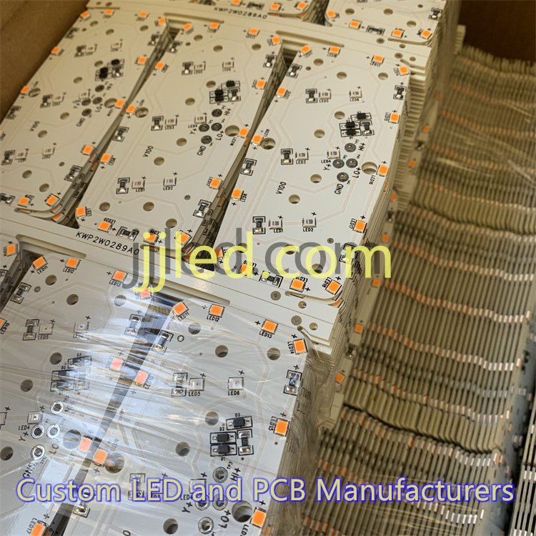
Aluminum PCBs are popular because they offer excellent thermal conductivity. This means they help spread heat away from the LEDs, keeping them cooler and extending their life. Plus, aluminum boards are lightweight, making them ideal for applications where weight matters, like automotive lighting.
Comparing FR4 vs. Ceramic substrates is crucial for high-heat environments. FR4 is cost-effective and widely used but can struggle with heat dissipation in powerful LED setups. Ceramic boards handle heat much better but come at a higher price. Choosing between them depends on your project budget and how much heat your LEDs generate.
Copper thickness on your PCB matters too. A standard range of 1 to 3 ounces of copper is recommended to ensure smooth current flow without overheating. Thicker copper allows more current, which is essential for high-power LEDs.
From a sustainability viewpoint, especially for EU users, sourcing eco-friendly materials is becoming a priority. Look for suppliers who offer recycled or low-impact substrates, which help meet environmental regulations while still providing reliable performance.
In short, picking the right materials—aluminum or ceramic, proper copper weight, and sustainable options—directly impacts thermal management, durability, and overall LED efficiency on your PCB.
Design Techniques for Optimal LED Circuit Boards
Creating a strong LED light circuit board design starts with a clear schematic. For beginners, tools like Altium or KiCad are great picks—they offer user-friendly interfaces and plenty of support. These programs help map out your LED driver circuit layout and make sure connections are clean from the start.
When it comes to the actual layout, think about wiring your LEDs in series and parallel combinations. This balances voltage and current for consistent brightness. Don’t forget thermal vias—small holes that channel heat away from hotspots—plus proper pad sizing to ensure reliable soldering and good electrical contact.
For dynamic lighting effects, multiplexing and RGB LED matrix designs are key. Multiplexing reduces the number of control lines needed, while matrixing allows complex light patterns without extra wiring. For example, a custom LED board prototype used in automotive taillights leverages these layout tricks to deliver bright, reliable signals that survive tough conditions.
In short, good schematic tools paired with smart layout strategies make all the difference in efficient, high-performance LED circuit board design.
Thermal Management: The Heart of Reliable LED Designs
Heat is the biggest enemy of any LED circuit board design. When LEDs get too hot, their lifespan drops fast, and light output dims. Managing this heat effectively is key to a reliable, long-lasting LED board.
Common heat challenges:
- High-power LEDs generate a lot of heat in a small space.
- Poor heat spread causes hotspots, damaging the LED and nearby components.
- Increased junction temperature lowers efficiency and color stability.
Proven solutions include:
- Heatsinks: Metal-core or aluminum LED circuit boards provide a solid base to pull heat away from the LEDs.
- Thermal vias: These vertical holes filled with copper connect heat from the top layers down to the metal core or heatsink.
- Simulation tools: Software like ANSYS helps predict heat flow and optimize the layout before building a prototype.
Best placement practices to reduce hotspots:
- Space high-power LEDs apart to allow heat to dissipate evenly.
- Position thermal vias directly under LED pads.
- Avoid trapping heat by leaving airflow paths around the board.
Pro tip for real-world reliability:
- Always run thermal tests under actual operating conditions. Measure LED temperature during on/off cycles to check for unexpected spikes.
- Make adjustments to heatsink size or add thermal interface materials if temperatures exceed safe limits.
Taking care with thermal management means your LED light PCB assembly will deliver consistent brightness while avoiding early failures. It’s a must-do step whether you’re working on automotive LED signaling boards, commercial panels, or smart home fixtures.
Assembly and Prototyping Best Practices for LED PCB Design
When it comes to mounting LEDs on your circuit board, choosing between Surface-Mount Technology (SMT) and Through-Hole really depends on your project’s needs.
- SMT is great for compact, high-volume LED PCBs. It’s faster to assemble and fits better in tight spaces.
- Through-Hole works well if you need extra mechanical strength or easier manual soldering, especially for prototypes or larger, high-power LEDs.
Step-by-Step Prototyping Guide
- Prepare your Gerber files carefully—these are the blueprints manufacturers use.
- Order a small batch prototype to test the physical layout.
- Inspect the board for soldering quality and component placement.
- Run initial electrical tests to verify power delivery and LED operation.
- Test under real-world conditions, like temperature and lighting variation.
Common Pitfalls to Avoid
- Soldering high-power LEDs without a reflow oven can cause uneven joints and damage.
- Overheating components during hand soldering is a common risk.
- Make sure your soldering iron temperature is well-controlled and you allow cooling between passes.
Driver Integration Tips
- Use constant current drivers for stable, flicker-free LED brightness.
- For dimming, PWM (Pulse Width Modulation) dimming integrates well—especially with RGB LED matrix designs—to maintain color accuracy and reduce heat.
- Ensure your driver layout matches the current and voltage specs of your LEDs to avoid failure.
By staying clear of these pitfalls and following proper assembly protocols, your custom LED PCB prototyping will be smooth and efficient, whether for automotive taillights, commercial signage, or smart home lighting.
Applications and Real-World Implementations of LED Light Circuit Board Design
LED circuit board design plays a huge role across many industries today. Here’s where custom LED PCB boards really shine:
Automotive LED Signaling Boards
Car manufacturers rely on tailored LED boards for brake lights, turn signals, and interior lighting. These boards must handle tough conditions—vibration, heat, moisture—while delivering bright, reliable light. Aluminum LED circuit boards and metal core PCBs are popular here for their strong thermal management and durability.
Commercial Backlit Signage and Displays
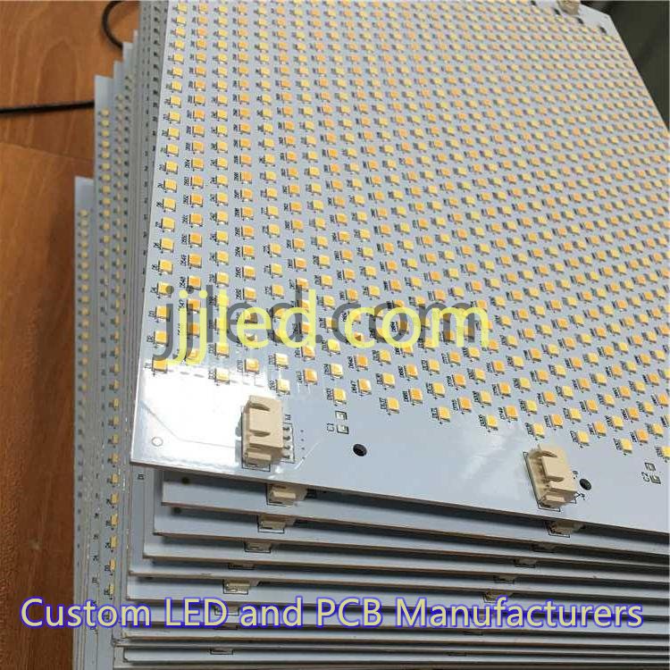
Retail stores, airports, and public spaces use custom LED PCB designs to power backlit signs and digital displays. These need uniform illumination and energy efficiency to run cost-effectively 24/7. Multiplexed RGB LED matrix designs help create dynamic visual effects that attract attention.
Residential Smart Lighting Fixtures
Smart homes increasingly feature LED boards integrated with IoT controls. Designers focus on energy-efficient LED PCB layouts that support dimming and color changing, often using PWM dimming drivers. Compact, multilayer LED light panels are common to fit modern fixture styles without sacrificing brightness.
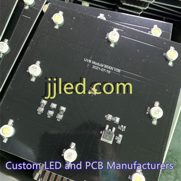
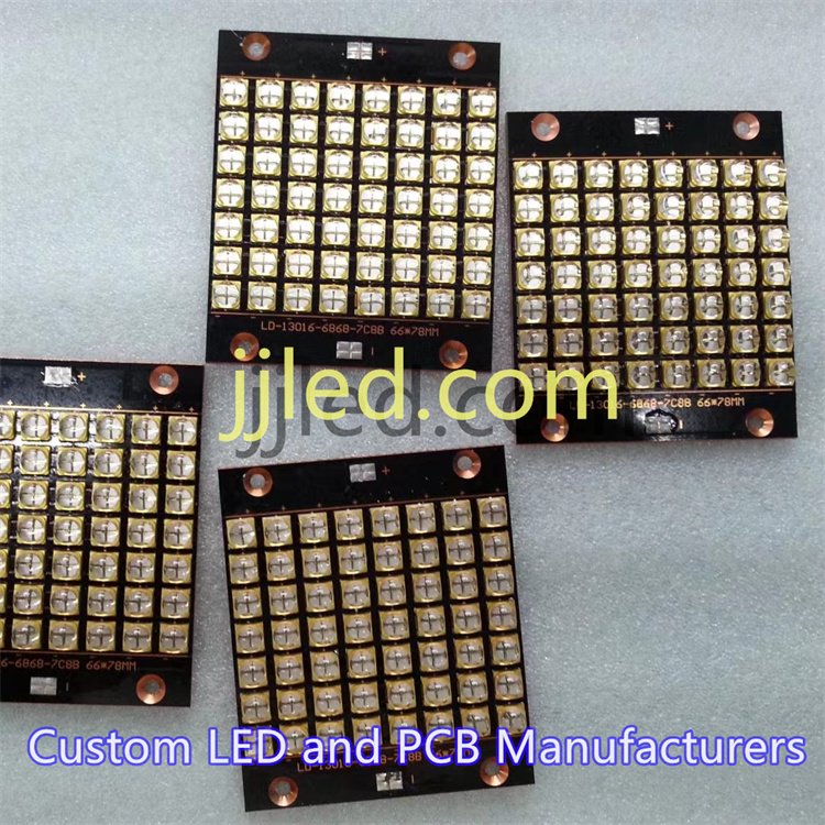
Emerging Trends: UV/IR LED Uses
New applications are pushing LED circuit board design into UV and IR lighting territory. These LEDs serve specialized industrial and medical roles: from sterilization to machine vision. Heat sinks and thermal management remain critical here, especially with high power LED board fabrication to handle more intense output.
In short, custom LED PCB prototyping and design adapt to diverse needs—whether for rugged automotive boards, eye-catching commercial signage, or smart residential setups. Staying updated on material choices and thermal management ensures your design performs reliably in any application.
Cost Considerations and Scalability with Custom LED Board
When designing a custom LED circuit board, understanding costs upfront is key. Here’s a quick breakdown:
- Material costs: Substrate type (aluminum, FR4, or ceramic), copper thickness, and components like LED drivers affect budget. Metal-core PCBs tend to cost more but offer better thermal performance.
- Labor and tooling: Assembly methods (SMT or through-hole), prototype runs, and tooling setup can add up fast.
- Energy savings vs. upfront investment: Calculate ROI by comparing long-term energy savings from efficient LED boards with your initial build costs. High-quality boards often pay off quickly through lower power use and longer lifespan.
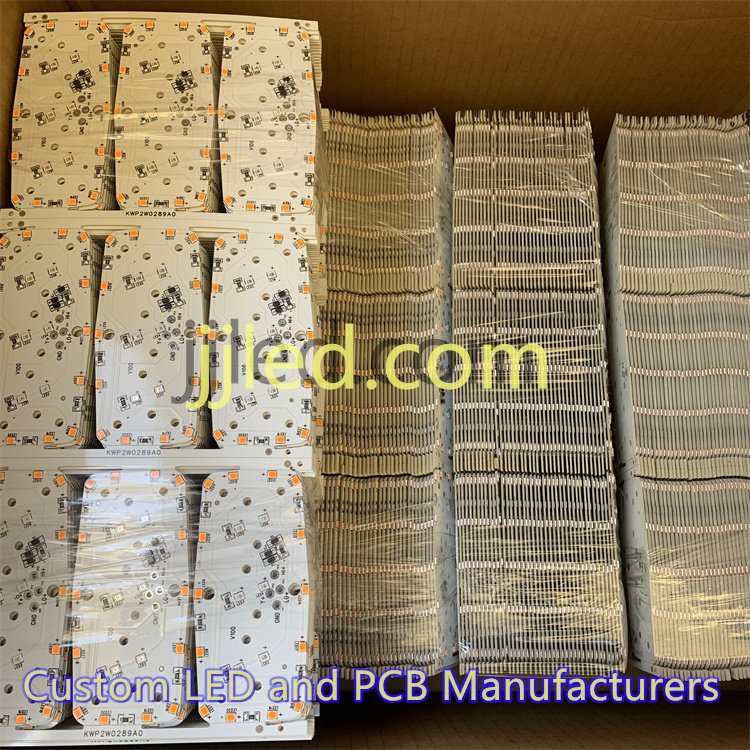
- Scaling production: Prototyping small batches (1–10 units) is affordable but expect unit prices to drop significantly when scaling to hundreds or thousands.
- Local shipping and delivery: For US and EU customers, fast shipping options and nearby manufacturing can reduce lead times and lower overall costs. Consider regional suppliers to ease logistics and comply with local standards.
Planning cost and scalability early helps you avoid surprises and build LED boards that fit your budget and growth plans.
Troubleshooting Common LED PCB Design Issues
When working on LED light circuit board design, some issues pop up frequently. Here’s a quick guide to tackle the most common ones:
Flickering Causes and Fixes
- Noise in traces: Flickering often happens when signal or power traces pick up interference. Keep power and ground traces short and thick to reduce noise.
- Loose connections: Double-check solder joints and connectors for stability.
- Inadequate filtering: Use capacitors close to the LED driver to smooth voltage fluctuations.
Overheating Diagnostics and Quick Remedies
- Check heat distribution: If some LEDs get hotter, inspect thermal vias and heat sink integration.
- Improve cooling: Add or upgrade heatsinks, use metal-core PCB boards, or increase copper thickness (1-3 oz) to improve heat dissipation.
- Simulation tools: Run thermal simulations before finalizing the design to spot hotspots early.
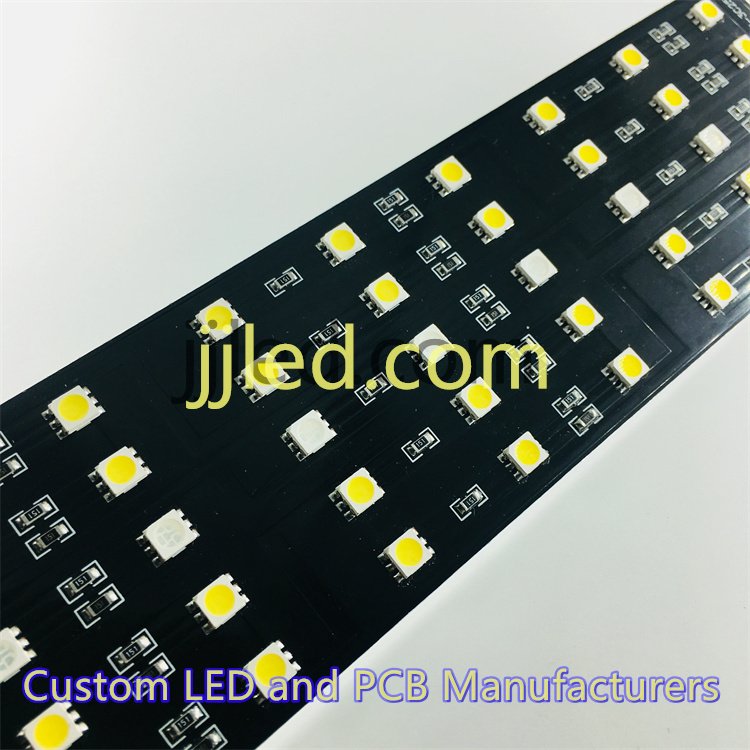
Color Consistency Tips for RGB Arrays
- Match LED bins: Use LEDs from the same production batch to avoid color variation.
- Calibrate drivers: Adjust current levels individually for each color channel.
- Uniform layout: Keep RGB elements evenly spaced and use consistent trace lengths to maintain signal integrity.
FAQ: Avoiding Capacitive Coupling in Dense Layouts
- Separate sensitive signals: Maintain physical spacing between high-frequency and low-frequency traces.
- Use ground planes: A solid ground layer reduces stray capacitance.
- Shielding tricks: Insert guard traces or ground fills near signal lines where needed.
- Controlled impedance: Design trace widths and spacing carefully for stable electrical characteristics.
By keeping these tips in mind, you can effectively troubleshoot and enhance your LED PCB board design, ensuring reliable and high-quality lighting solutions for various applications globally.
