
Understanding 2835 SMD LED Specifications
To design an effective PCB for 2835 SMD LEDs, start by knowing their key specifications.
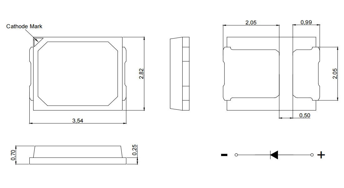
Package Dimensions and Pin Layout
The 2835 LED measures approximately 2.8 mm x 3.5 mm. It features:
- Anode and cathode pads for electrical connections
- A thermal pad centrally located to help dissipate heat directly to the PCB
This compact footprint demands precise pad design for reliability.
Electrical Characteristics
Typical operating values include:
| Parameter | Value Range | Notes |
|---|---|---|
| Forward Voltage (Vf) | 2.8 – 3.4 V | Depends on color & current |
| Forward Current | 60 mA (typical), up to 150 mA | High-current variants available |
| Power Rating | 0.2 W to 1 W | Choose based on brightness need |
Understanding these helps in sizing traces and power regulation.
Optical and Thermal Properties
- Luminous efficacy: Usually between 80–120 lm/W, depending on chip quality
- Beam angle: Roughly 120°, offering wide light coverage
- Junction temperature limits: Maximum around 120°C; exceeding this reduces lifespan and efficiency
Proper thermal design safeguards LED performance and longevity.
Mastering these specs ensures the PCB layout supports both electrical and thermal demands effectively, laying a strong foundation for your 2835 SMD LED projects.
Selecting the Right PCB Substrate for 2835 SMD LEDs
Choosing the right PCB substrate is crucial when designing for 2835 SMD LEDs, as it directly affects thermal management, performance, and durability. The most common options are FR-4 and metal-core boards, usually made of aluminum or copper.
- FR-4 boards are cost-effective and suitable for low to moderate power LED arrays. They work well in applications where heat generation is limited and the environment isn’t too harsh. However, their thermal conductivity is relatively low, so they may struggle with heat dissipation for high-brightness or high-density layouts.
- Metal-core PCBs, especially aluminum-based boards, offer superior heat dissipation thanks to their metal base, which efficiently spreads heat away from the LEDs. This makes them ideal for powerful 2835 SMD LEDs and dense LED arrays that generate substantial heat. Copper-core PCBs, though less common, provide even better thermal conductivity but at a higher cost.
Factors influencing your substrate choice include:
- Power density: Higher wattage or more LEDs packed together call for metal-core PCBs.
- Operating environment: Areas with poor airflow or higher temperature ranges benefit from metal-base substrates.
- Budget constraints: FR-4 is cheaper, but sometimes investing in metal-core boards saves money long term by preventing thermal issues.
For demanding applications involving high-brightness 2835 LED arrays, we typically recommend metal-core PCBs to maintain optimal performance and longevity.
Discover more about high-power LED solutions by checking out our specialized custom aluminum LED PCBs designed for enhanced thermal management and reliability.
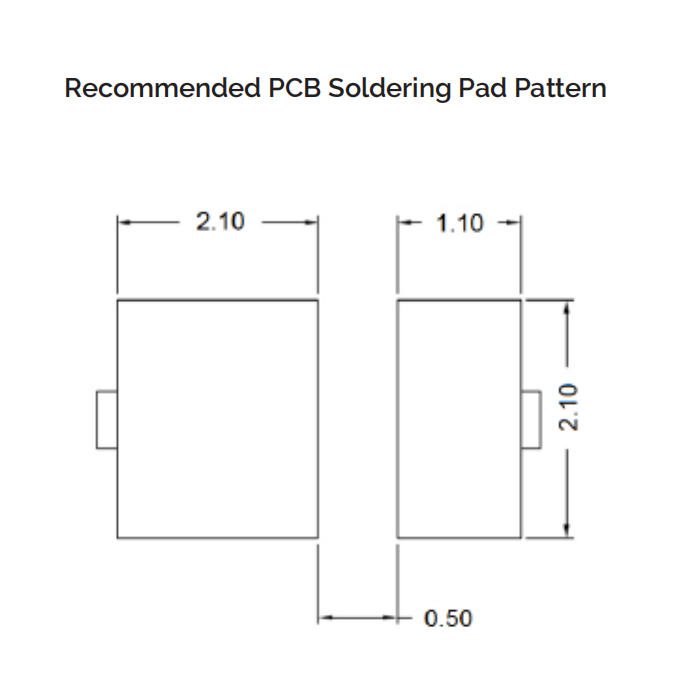
Creating the Correct Footprint for 2835 SMD LEDs
When laying out a PCB for 2835 SMD LEDs, getting the footprint right is critical for a reliable and strong solder joint. Start by checking the standard land pattern dimensions provided in the LED datasheet—this ensures the pads match the package size perfectly. The typical 2835 LED package measures about 3.5mm x 2.8mm, so your pad design should accommodate these dimensions precisely.
Pad sizing and spacing should allow enough room for solder paste without causing bridging or shorts. Generally, the anode and cathode pads are placed with consistent spacing to support easy pick-and-place assembly. Make sure to include a thermal pad if your LED package offers one; this is key to improving heat dissipation and mechanical stability. Proper thermal pad integration means matching the PCB copper area below the LED, often using thermal vias to conduct heat away efficiently.
Don’t overlook solder mask clearance around pads. Keeping the solder mask from overlapping pads helps avoid solder shorts and increases joint strength during reflow. Plus, it\’s essential to mark polarity clearly—2835 LEDs rely on correct anode and cathode orientation to function. Use a clear silk screen indicator or a small notch near the anode to signal correct placement.
For reference and detailed info about 2835 LED footprints and pad designs, the datasheet at JJLED provides trusted specifications to base your design on.
Key points:
- Use datasheet land pattern dimensions (approx. 3.5 x 2.8 mm).
- Design pads for both electrical and thermal contact, including thermal pads with vias.
- Maintain proper solder mask clearance to prevent shorts.
- Clearly mark polarity for hassle-free assembly and functionality.
This approach to the 2835 SMD LED footprint supports consistent solder quality and long LED lifespan in your custom LED PCB layouts.
Essential Thermal Management Strategies for 2835 SMD LED PCBs
Managing heat effectively is crucial when laying out a PCB for 2835 SMD LEDs, especially in high-brightness or dense LED arrays. Copper pours on the PCB serve as large, low-resistance areas that help spread heat away from the LEDs, minimizing hotspots. Adding thermal vias beneath the LED pads creates a direct heat path from the top layer to inner or bottom copper layers, boosting heat dissipation through the PCB substrate.
Extended thermal pads on the footprint enhance solder joint reliability and improve thermal conduction. Be sure to size these pads correctly according to the datasheet to avoid solder bridging while maximizing heat transfer.
To estimate heat dissipation needs, multiply the number of LEDs by their forward current and power consumption. This helps determine how much heat the PCB must manage. For setups with many 2835 LEDs or higher drive currents, consider integrating metal core PCBs (often aluminum-based) or multi-layer boards targeting thermal performance.
In demanding applications, pairing good PCB thermal design with external heatsinks or cooling solutions can prevent junction temperature from exceeding safe limits, thus extending LED lifespan and maintaining luminous output. Using copper pours, thermal vias, and extended pads together creates an efficient thermal path, ensuring stable electrical and optical performance.
For detailed guidance on LED driver integration alongside thermal design, check out our insights on LED driver circuit design.
Component Placement Best Practices for 2835 SMD LEDs
When laying out a custom 2835 LED light PCB board, the way you place each LED plays a big role in achieving bright, even illumination. Here are some key points to keep in mind:
- Uniform Light Distribution: Arrange the LEDs in consistent grids or rows to avoid hotspots or dark spots. Custom patterns can work too, but plan them carefully to maintain balanced luminous uniformity design across your panel.
- Spacing for Shadow Reduction and Airflow: Leave enough space between LEDs to prevent shadowing where one LED blocks another’s light. This spacing also helps improve airflow around each LED, which is crucial for thermal management and prolonging LED life.
- Support Components Positioning: Place resistors, drivers, and any other supporting parts near the LEDs but arranged so they don\’t block light or overhear. Grouping drivers and control electronics away from heat-sensitive LEDs helps maintain stable performance.
Following these guidelines ensures your PCB not only works efficiently but also maintains strong, even lighting suitable for all applications. For more about the 2835 LED\’s capabilities and design parameters, check out our detailed 2835 SMD LED chip overview.
Trace Routing and Electrical Design for 2835 SMD LEDs
When laying out a PCB for 2835 SMD LEDs, paying attention to trace routing and electrical design is crucial for performance and reliability.
Trace width calculations must be done carefully to handle the current without excessive voltage drop or overheating. Use wider power traces especially when driving multiple LEDs in parallel to ensure efficient current flow and maintain consistent brightness. Tools like IPC-2152 can help determine the right copper thickness and trace width based on your board’s current load.
Choosing between series and parallel configurations depends on your power supply and the number of LEDs. Series wiring simplifies current control because the same current runs through all LEDs, but it raises total voltage requirements. Parallel arrangements require thicker traces and careful current sharing to prevent uneven brightness or overheating. Often, a mixed approach with groups of series LEDs connected in parallel works best for balanced current sharing.
Incorporate a solid ground plane across your PCB to improve heat dissipation and reduce electromagnetic interference (EMI). A continuous ground layer minimizes noise and helps stabilize the LED driver circuitry. Additionally, careful routing of signal and power lines, keeping them short and avoiding sharp bends, further reduces potential interference issues.
For detailed design and fabrication options tailored to LED PCBs, consider exploring reliable suppliers offering specialized layouts like aluminum-backed PCBs or flexible LED boards to optimize electrical and thermal performance, such as the designs found on JJLED’s LED flexible PCB product page.
By balancing trace width, layout topology, and grounding strategies, you ensure your 2835 LED PCB delivers steady current, minimal voltage drop, and reduced EMI—key factors for a high-quality LED lighting solution.
Advanced Layout Considerations for 2835 SMD LED PCBs
When designing PCBs for 2835 SMD LEDs, taking advanced layout steps can make a huge difference, especially for complex lighting setups. Using multi-layer boards offers better routing flexibility and improved thermal management. With extra layers, you can separate power and ground planes, reduce electromagnetic interference, and add dedicated heat-spreading layers that help keep LED junction temperatures in check.
Integrating key features like LED drivers, dimming circuits, or protection components directly on the PCB adds value and improves reliability. For example, placing low-dropout regulators or PWM dimmers close to LEDs reduces noise and voltage drop issues. Overcurrent and reverse polarity protection can be designed into the board to prevent damage during installation or operation.
To ensure smooth manufacturing, focus on design-for-manufacturability (DFM). This means creating footprints that perfectly match recommended solder paste stencil openings for the 2835 LED pads, which ensures good solder joints without bridging or tombstoning. Also, make sure your layout supports standard reflow soldering profiles – uniform pad sizes, proper thermal reliefs, and clear solder mask openings help avoid solder defects and improve yields.
For more on the benefits of smart PCB choices with metal cores and thermal strategies, check out our detailed look at advantages of aluminum LED PCBs.
Key tips for advanced layouts:
- Use multi-layer boards to separate signal, power, and heat management layers
- Incorporate driver circuits and dimming features close to LED arrays to cut losses
- Add protection components in key places to extend LED lifespan
- Follow solder paste stencil guidelines for consistent reflow soldering quality
- Optimize pad design for minimal thermal stress and good solder wetting
The right advanced layout ensures your 2835 SMD LED PCB performs well, lasts long, and is easy to produce at scale.
Tools and Software for PCB Layout
Choosing the right tools is crucial for designing an efficient and reliable 2835 SMD LED PCB. Popular software like Altium Designer, KiCad, and Eagle provide solid options for schematic capture and layout. These platforms support easy importing of 2835 SMD LED footprint libraries, which helps ensure accurate pad dimensions and polarity markings, reducing errors during manufacturing.
When setting up your LED array placement and trace routing, it\’s wise to run simulations that check both thermal and electrical performance. Many tools offer thermal analysis features to predict heat buildup, letting you optimize copper pours, thermal vias, and trace widths before production. Electrical simulations also help verify current sharing in LED circuits and identify potential voltage drop problems.
For custom LED PCB fabrication, integrating these software capabilities streamlines design iterations and boosts confidence in your final output. If you’re looking to assemble or prototype, consider services that support full PCB assembly along with design validation, such as JJLED’s comprehensive LED PCB assembly services.
In , investing time in mastering these tools ensures your 2835 SMD LED layouts perform well in both illumination and durability.
Common Issues and How to Fix Them in 2835 SMD LED PCB Layout
When designing a PCB for 2835 SMD LEDs, a few mistakes often cause trouble down the line. Ignoring heat buildup is a top culprit — inadequate thermal management leads to overheating, which shortens LED life or causes flickering. Use enough thermal vias in LED boards and copper pours to keep temperatures in check.
Uneven current distribution also causes problems, especially with densely packed arrays. Always double-check your circuit for balanced current sharing to avoid some LEDs burning out early while others underperform. This is crucial for stable brightness and long-term reliability.
Polarity errors are another common headache. 2835 SMD LEDs have a clear anode and cathode; mismatching these pins or poor pad alignment can prevent lighting or damage LEDs during soldering. Make polarity marking on your PCB footprint unmistakable to reduce risks.
Here are quick fixes for typical issues:
- Dimming or uneven brightness: Verify trace widths and solder joints; small voltage drops can cause this effect.
- Flickering: Check for loose connections and stable current sources.
- Premature failure: Improve heat dissipation using metal core substrate options, such as aluminum PCB for LEDs, or add more thermal vias to help dissipate heat better.
For reliable LED performance, always inspect your layout for these pitfalls ahead of time. If you want to explore advanced thermal solutions or custom LED PCB fabrication strategies, take a look at our detailed offerings on custom LED light PCB boards.
Avoiding these common mistakes saves time and ensures your 2835 SMD LED setups shine consistently without early headaches.
Testing and Validation for 2835 SMD LED PCBs
Once your PCB layout for 2835 SMD LEDs is complete, thorough testing and validation are critical to ensure the board performs reliably. Start with prototype checks to verify basic functionality—confirm that each LED lights up correctly without flicker or dimming. Use thermal monitoring tools to measure the junction and PCB temperatures during operation, ensuring your LED PCB thermal management solutions effectively keep heat within specified limits.
Light uniformity is another key factor. Check the LED array placement and spacing on your prototype for even brightness, avoiding hotspots or shadows, which can affect the overall visual quality. This step helps validate your design choices, such as trace routing and copper pours.
For long-term reliability, conduct stress tests by running the LEDs at rated or elevated currents over extended periods. This helps reveal issues like uneven current distribution or solder joint failures. Adjustments may be necessary if you spot early signs of component degradation.
For reliable designs, consider incorporating practices recommended on professional custom LED board pages like the 2835 LED light PCB board, which provides insights into common manufacturing and testing standards.
In , a solid testing phase covers:
- Confirming functionality and correct polarity
- Monitoring temperature to prevent overheating
- Evaluating luminous uniformity across the LED array
- Assessing durability through prolonged current load
These steps ensure your 2835 SMD LED PCB meets both performance and longevity expectations for your application.
