
Understanding PWM Dimming for LEDs
Have you ever wondered how PWM LED dimming works so smoothly without changing the color or quality of your LED lights? The secret lies in how PWM (Pulse Width Modulation) controls the brightness by adjusting the duty cycle — the ratio of ON to OFF time in each cycle.
How PWM Controls LED Brightness
Instead of lowering the voltage, PWM rapidly switches the LED on and off at a frequency that’s so fast our eyes can’t detect flickering. The average power delivered to the LED changes based on the duty cycle:
- Higher duty cycle (e.g., 80%) means the LED is ON longer, resulting in brighter light.
- Lower duty cycle (e.g., 20%) means the LED is ON less, dimming the light.
This method keeps the LED’s color stable and efficient since the LED is always driving full current during ON time.
Recommended PWM Frequencies for Flicker-Free Operation
To avoid visible flicker, especially with sensitive eyes or video capture, it’s best to use PWM frequencies between 200 Hz and 1000 Hz. Frequencies in this range ensure:
- No annoying flicker to the human eye
- Smooth and consistent dimming effect
- Compatibility with most LED strips and modules designed for PWM control
Why Constant Voltage LEDs Benefit from Low-Side Switching
Most constant voltage LED strips and modules perform best when switched on the low side—meaning the MOSFET is placed between the LED’s negative terminal and ground. Here’s why:
- Simpler wiring and control using an N-channel MOSFET with logic-level input.
- Safer and easier to drive from typical microcontrollers like Arduino or ESP32.
- Reduced noise and more stable voltage across the LED load.
By switching the low side, you keep the LED voltage stable, which helps maintain consistent brightness and color temperature.
Key Takeaway: Properly setting your PWM frequency and choosing a low-side switching approach ensures flicker-free, efficient LED dimming with stable light quality. This foundation makes selecting the right logic-level MOSFET and designing your PWM LED dimmer circuit much easier.
Ready for the next step? Let’s explore why choosing the right MOSFET is crucial for your PWM LED dimmer.
Why Use a MOSFET in PWM LED Dimmers?
MOSFETs are the go-to choice for PWM LED dimmers because they offer lower losses and higher efficiency compared to BJTs. With MOSFETs, you get faster switching and less heat generation, which is key for smooth LED dimming without wasting power.
N-Channel vs. P-Channel MOSFETs
| Feature | N-Channel MOSFET | P-Channel MOSFET |
|---|---|---|
| Switching Side | Low-side switching (ground side) | High-side switching (power side) |
| On-Resistance | Usually lower (better efficiency) | Typically higher |
| Gate Drive | Easier to drive (logic-level MOSFETs common) | Requires higher gate voltage |
| Cost & Availability | More common and cheaper | Less common, usually pricier |
Because N-channel MOSFETs have lower RDS(on) and are easier to drive directly from MCU logic levels, they’re preferred for low-side switching setups in custom LED dimmer controller switch boards. P-channel devices, while useful for high-side switching, come with trade-offs like higher resistance and gate drive complexity.
Role in Custom LED Dimmer Controller Switch Boards
In our custom LED dimmer controller switch boards, MOSFETs act as fast, reliable switches that handle high currents safely and efficiently. Selecting the right MOSFET ensures better dimming precision, less heat, and longer LED lifespan. This is why these boards often feature N-channel logic-level MOSFETs optimized for PWM LED dimming.
For high-performance and reliable PWM LED control, check out our range of tailored PWM LED dimmer controller switch boards designed specifically to support these MOSFET characteristics.
Key MOSFET Parameters to Evaluate for PWM LED Dimmers
Choosing the right MOSFET for your PWM LED dimmer means looking closely at several important specs. Here’s what matters most:
| Parameter | What It Means | Recommended Value |
|---|---|---|
| VDS (Drain-Source Voltage) | Max voltage MOSFET can withstand between drain and source | Should be at least 20V for a 12V LED system (with margin) |
| ID (Continuous Drain Current) | Max current the MOSFET can handle continuously | 1.5 to 2 times your max LED current for safety |
| RDS(on) (On-Resistance) | Resistance when MOSFET is on; lower means less heat and voltage drop | Below 50 mΩ for efficient dimming and less power loss |
| VGS(th) (Gate Threshold Voltage) | Minimum gate voltage MOSFET needs to start conducting | Logic-level, under 2-3V, ideal for 3.3V/5V microcontrollers |
| Qg (Total Gate Charge) | Amount of charge needed to switch the MOSFET gate | Lower values for faster switching and less energy loss at higher PWM frequencies |
| Package & Thermal | Physical size and heat dissipation ability | TO-220 packages are common for easy heat sinking; calculate power dissipation to avoid overheating |
These key MOSFET parameters ensure your LED dimmer runs smoothly, stays efficient, and avoids issues like heat buildup or slow switching. For more design tips related to LED circuit boards, check out our guide on design considerations for LED circuit boards.
Logic-Level vs. Standard MOSFETs
When selecting a MOSFET for PWM LED dimmer circuits, understanding the difference between logic-level and standard MOSFETs is crucial.
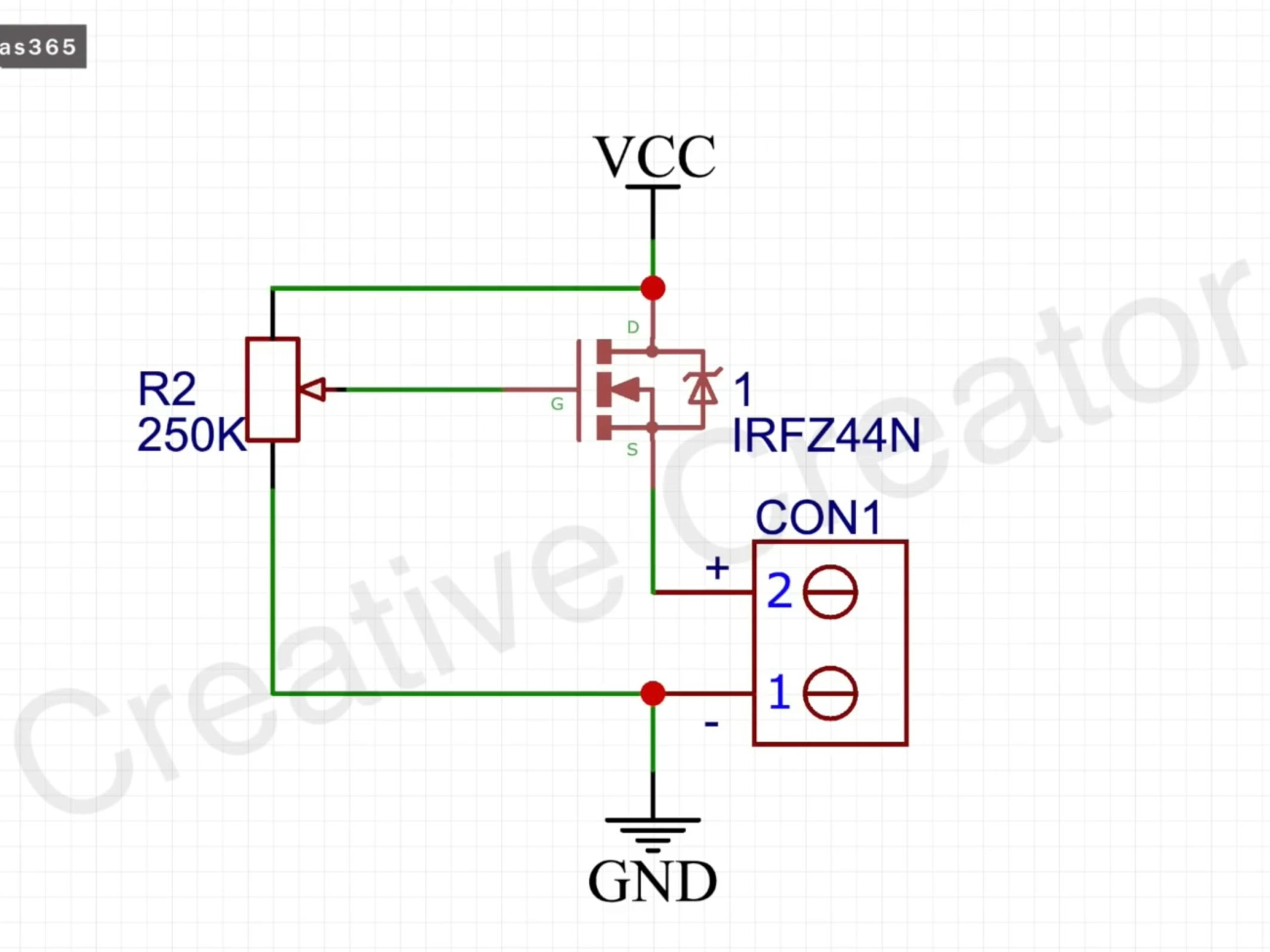
Why Standard MOSFETs Struggle with 5V Gates:
Standard MOSFETs like the IRFZ44N require a higher gate voltage (VGS) — usually around 10V — to fully turn on. If you\’re driving them directly from a 3.3V or 5V microcontroller pin, they won’t fully open. This leads to higher RDS(on), causing excessive heat and poor efficiency in your LED dimmer circuit.
Benefits of Logic-Level MOSFETs:
Logic-level MOSFETs are designed with a low VGS(th), often below 2-3V. This means they fully switch on at typical MCU output voltages (3.3V or 5V). These MOSFETs offer:
- Lower RDS(on) at logic voltages → less heat and power loss
- Direct control from microcontrollers like Arduino or ESP32 without extra drivers
- Faster switching speeds for smooth PWM dimming with less EMI
| Parameter | IRFZ44N (Standard) | IRLZ44N (Logic-Level) |
|---|---|---|
| VGS(th) | ~4V | ~1.0 – 2.0V |
| RDS(on) @ 5V | High | Low (< 50 mΩ) |
| Suitable Gate V | 10V+ | 3.3V / 5V |
| Ideal Use | High-voltage, driver circuit needed | Direct MCU drive, LED dimmer |
If you want a hassle-free LED strip dimmer circuit that runs on common 3.3V or 5V controllers, logic-level MOSFETs are the way to go.
For more design tips on LED circuits and PWM LED PCB applications, check out our detailed LED light circuit board design guides.
Recommended MOSFETs for PWM LED Dimmers
Choosing the right MOSFET is crucial for efficient PWM LED dimming. Here’s a quick rundown of popular and reliable options:
Budget and Popular Choices
IRLZ44N: A widely-used N-channel logic-level MOSFET, great for 12V LED strip dimmers. It offers a low RDS(on) around 22mΩ and a VDS of 55V, well above typical LED supply voltages.
IRF3205: Another N-channel option with a higher current rating and low RDS(on), perfect for low-cost projects needing around 30A continuous current.High-Current MOSFETs
For heavy-duty PWM LED dimmers, consider the PSMN series (like PSMN2R8-80BS) or AOI MOSFETs, which provide ultra-low RDS(on) (below 5mΩ) and high current capacity (over 100A), ideal for large LED arrays and professional lighting setups.
P-Channel MOSFETs for High-Side Switching
When your design requires high-side PWM control, P-channel MOSFETs such as the IRF9540 or AO4407 are common. They have slightly higher RDS(on) and slower switching speeds but simplify wiring for certain LED dimmer circuits.
| MOSFET Model | VDS (V) | ID (A) | RDS(on) (mΩ) | Gate Threshold (V) | Approx. Price (USD) |
|---|---|---|---|---|---|
| IRLZ44N | 55 | 47 | 22 | 1-2 | $1 – $2 |
| IRF3205 | 55 | 110 | 8 | 2-4 | $1 – $2 |
| PSMN2R8-80BS | 80 | 100+ | 2.8 | 1-2 | $3 – $5 |
| AOI3416A | 30 | 60 | 3.7 | 1-2 | $2 – $4 |
| IRF9540 | -100 | -23 | 120 | 2-4 | $1 – $3 |
| AO4407 | -40 | -30 | 25 | 2-4 | $1 – $3 |
For most DIY and commercial PWM LED dimmer projects, N-channel logic-level MOSFETs like the IRLZ44N balance performance and cost effectively. If you\’re looking to scale or improve efficiency further, upgrading to high-current PSMN or AOI series devices is a smart move.
Selecting MOSFETs with low RDS(on), suitable VDS ratings, and logic-level gates ensures smooth, flicker-free PWM dimming for LED strips and lighting fixtures. For custom PWM LED controller designs, using MOSFETs aligned to these parameters optimizes power dissipation and switching performance.
For more detailed insights into custom LED PCBs and dimmer boards, check our resources on advantages of aluminum LED PCBs and expert LED PCBA custom manufacturing.
Building a Basic PWM LED Dimmer Circuit
When building a PWM LED dimmer circuit, a common and effective approach is using a low-side N-channel MOSFET. This setup places the MOSFET between the LED load and ground, making switching easier and more efficient. Key components include:
- Gate resistor: A small resistor (100Ω to 220Ω) placed between the MCU output and MOSFET gate limits inrush current, protecting your microcontroller.
- Pull-down resistor: A 10kΩ resistor from gate to ground ensures the MOSFET stays off when the MCU pin is disconnected or during startup, preventing unintended LED flicker.
For higher PWM frequencies or larger LED loads, adding a gate driver helps switch the MOSFET faster and more cleanly by providing adequate gate charge current. This reduces switching losses and improves efficiency, especially important for high-current LED dimmers.
If you need to control LEDs on the high side (between power supply and LED), a P-channel MOSFET can be used. However, high-side switching is more complex due to the need for level shifting and proper gate drive voltage. It\’s often reserved for specific designs where low-side switching isn\’t practical.
Safety components should never be overlooked:
- A flyback diode (or freewheeling diode) protects the MOSFET and other parts from voltage spikes caused by inductive elements in the circuit.
- Heatsinking is critical when driving high currents or continuous loads. Using packages like TO-220 with proper thermal pads and heat sinks ensures reliable operation and prolonged MOSFET life.
For practical low-side MOSFET dimmer designs and LED driver circuits, check out our detailed PCB designs and white LED light circuit PCB boards that showcase these principles in action.
Common Issues and Troubleshooting in PWM LED Dimmers

When working with PWM LED dimmers using MOSFETs, a few common issues can pop up, but they’re usually easy to fix once you know what to look for.
- Slow rise/fall times: This often comes down to gate capacitance. MOSFETs have a certain gate charge (Qg), and if your driver (like an Arduino or other MCU) can’t supply enough current, switching slows down. Slow switching means higher losses and more heat. Using a MOSFET with low gate charge or adding a dedicated gate driver can fix this.
- Heat buildup and efficiency losses: Low RDS(on) MOSFETs are essential here. If the MOSFET isn’t fully on or has too high resistance, it dissipates more power as heat. Make sure to pick devices rated with low RDS(on) and proper current capacity, and consider heatsinking (like a TO-220 package) to keep temperatures in check.
- Flicker at low duty cycles: Flickering usually happens if your PWM frequency is too low or due to unstable switching. Recommended switching frequencies (200-1000 Hz) help keep LED flicker invisible to the eye. Also, ensure your MOSFET switches cleanly without partial conduction during transitions.
- EMI/RFI reduction: Fast switching edges can cause electromagnetic interference. To reduce EMI, use gate resistors to slow the switching speed slightly, add snubber circuits where necessary, and keep wiring neat and short. Shielding and proper PCB layout also play a big role when designing custom PWM LED controller switch boards.
Addressing these issues improves lifespan, reliability, and the overall performance of your PWM LED dimmer. For high-quality, pre-designed solutions, exploring specialized PWM LED controller switch boards can save time and effort.
Advanced Tips for Custom LED Dimmer Controllers
When building custom PWM LED dimmer controllers, integrating with popular microcontrollers like Arduino or ESP32 is a great way to add flexibility and precision. Simple code snippets allow easy control of PWM frequency and duty cycle, letting you fine-tune LED brightness smoothly. For example, using Arduino’s analogWrite() or ESP32’s dedicated LED PWM APIs, you can drive logic-level MOSFET LED drivers directly.
If you’re scaling up to multi-channel or high-power setups, consider these points:
- Use MOSFETs with low RDS(on) and proper gate charge (Qg) for efficient switching at higher loads.
- Add separate gate drivers to handle faster rise/fall times and protect your microcontroller.
- Implement thermal management with adequate heatsinking to avoid overheating during extended use.
- Design your PCB layout carefully, minimizing noise and EMI while ensuring stable power delivery.
Choosing a dedicated PWM LED PCB board designed for dimming adds reliability and simplifies your project. These boards typically include optimized MOSFET arrangements, built-in protections, and thermal solutions tailored for LED strips and modules. This approach saves time and reduces troubleshooting, especially in complex or high-current applications.
For reliable and customizable solutions, check out our range of PWM LED PCB offerings, featuring high-quality components suited for advanced dimmer controllers. See options like our custom PWM LED controller switch boards for hassle-free integration into your LED lighting projects.
Explore more about our PWM LED PCB boards crafted to meet diverse dimming and control needs.
Commercial Alternatives: Custom LED Dimmer Controller Switch Boards
When it comes to PWM LED dimming, pre-built PWM LED controller switch boards offer a hassle-free solution. These custom boards are designed for easy plug-and-play use, providing built-in protection features such as overcurrent and thermal shutdown. This means better reliability and safety compared to DIY setups, especially in high-power or multi-channel applications.
Benefits of Pre-built PWM LED Dimmer Boards
- Ready to use: No complex circuit design or component sourcing required
- Protection features: Overload, short circuit, and thermal protection included
- Improved reliability: Designed for consistent performance and heat management
- Compact and neat: Professional PCB layout reduces EMI and improves efficiency
- Scalable: Often support multi-channel LED dimming for advanced lighting systems
When to DIY vs. Buy Custom LED Dimmer Boards
| Scenario | Recommendation | Reason |
|---|---|---|
| Prototyping & Testing | DIY low-side MOSFET driver | Flexibility and cost-effective for small-scale use |
| Small projects | DIY or budget boards | Suitable if you know basic MOSFET PWM selection |
| Production & Scaling | Pre-built custom PWM LED dimmer | Ensures reliability, protection, and compliance |
| High-current setups | Pre-built with heatsinks | Better thermal management and durability |
For those building LED lighting systems, especially using our reliable LED PCB boards, choosing between DIY and commercial options depends on your project size and priorities. Pre-assembled boards make sense when you need consistency and protection, while DIY routes suit learning and small-scale implementation.
By selecting the right custom PWM LED controller switch board, you reduce wiring complexity, improve heat dissipation, and streamline your LED dimming control—ultimately saving time and preventing common MOSFET issues in PWM LED dimmer circuits.
